Cylindrical Infrared Thermography Sensors
continuous thermography monitoring
for NFPA 70B & FM compliance
(cylindrical form factor)
for NFPA 70B & FM compliance
(cylindrical form factor)
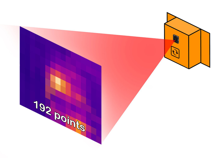
Continuous Thermography Monitoring — a full live thermal image, not single-point measurement.
Replaces periodic manual IR surveys for NFPA 70B electrical maintenance & FM Global Data Sheet 5-19.
NFPA 70B aligned: ΔT between zones & ΔT vs ambient.
Patented thermal imaging in 2 resolutions (XS / S).
Requires the M-C-THIMG-2HUB connection hub.
Open protocols: Modbus TCP & RTU, BACnet/IP, SNMP & MQTT.
Up to 768 measurement points per image
Refreshed every 2 seconds.
M24 mount form factor.
UL listed.
thermography sensors form factors
 Cylindrical
You are here

Field of View Calculator
Match the right sensor and mounting distance to your switchgear or panel — interactive coverage & distance calculator for both resolutions.
NFPA 70B (2026)
Mandatory since 2023 and referenced by OSHA. It permits permanently-installed continuous thermal monitoring — exactly what we provide.
FM Global DS 5-19
FM's switchgear loss-prevention data sheet recommends continuous thermal monitoring systems — for 24x7 risk reduction and lower insurance risk.
Switchgear, Panel & Transformer Monitoring
Continuous, automated 24x7 thermal monitoring of switchgear, panels and transformers — replacing individual contact probes and periodic camera-gun scans.
Logical Thermal Zones
Split one thermal image into 4 logical sensors — one per bus bar or feeder cable — each reported as a discrete Modbus sensor.
Phase Unbalance Detection
Compare phase temperatures to surface hot spots and thermal imbalance before they overheat and damage switchgear.
Open Industrial Protocols
Integrates with your EPMS over Modbus TCP and Modbus RTU, and your BMS over BACnet/IP — plus SNMP and MQTT, all through the S-BASE-7 base unit.
Patented Continuous Thermography
A full, live thermal image — up to 768 points, refreshed every 2 s, 24x7 — not the single-point reading of a spot or contact sensor. Patented.
Catch Problems Before Failure
Surface overheating from loose connections, overloaded circuits or failing components — before it becomes equipment failure or fire.
2 Resolutions & Specs
192 and 768 measurement points. Compare both versions — resolution, field of view, range and accuracy.
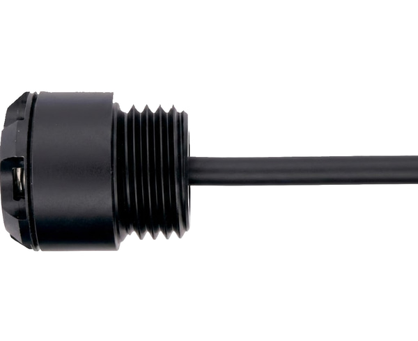
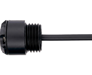
Cylindrical Mount
A compact, probe-style cylindrical housing for flexible placement in tight spaces — available in X-Small & Small, connected via the M-C-THIMG-2HUB hub. Rack/wall, DIN-rail & IR-window versions also available.
Patented Continuous Thermography Monitoring
A traditional spot or contact temperature sensor reports one number, at one fixed location. A manual thermal-camera survey is a snapshot taken only a few times a year. Both leave blind spots — in space (everywhere the probe isn't) and in time (every hour between scans).
Continuous Thermography Monitoring removes both. The sensor turns an entire surface into a live thermal image — up to 768 measurement points, refreshed every 2 seconds, 24x7 and automatically. A developing hot spot is caught wherever and whenever it appears, with no one scanning energized equipment by hand.
One image scales from 192 points (X-Small) to 768 (Small), and is available over Modbus TCP, Modbus RTU (RS-485), SNMP and MQTT. This is the continuous thermographic monitoring that NFPA 70B electrical maintenance programs and FM Global Data Sheet 5-19 call for.
The technology is protected by a family of patents (inventor: Maarten Van Laere):
- Thermography sensor — US 10,455,166
- Daisy-chained thermography sensors — US 12,253,416
- IR-window-mounted thermography sensor — US 12,292,334
Switchgear, Panel & Transformer Monitoring
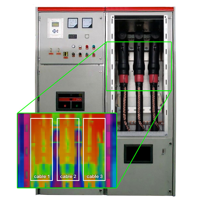
Traditionally switchgear, panels and transformers are monitored with contact-based temperature sensors that only report the temperature at the point where the sensor is mounted, supplemented by periodic thermal camera-gun scans. You hope to catch an issue the moment it appears — and that it does not surface just after a scan.
With our patented thermography sensors you monitor switchgear, electrical panels and transformers 24x7 in a fully automated way — no individual temperature sensors required.
With our patented thermography sensors you monitor switchgear, electrical panels and transformers 24x7 in a fully automated way — no individual temperature sensors required.

Logical Thermal Zones
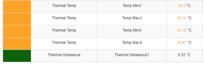
The thermography from each sensor can be divided into 4 different logical temperature sensors. This lets you report each bus bar, feeder cable or equipment part as a discrete temperature sensor over Modbus TCP.
For the Medium & Large versions, the sensor reports the MIN and MAX value in each zone. For the Small and X-Small versions, the sensor reports the MAX temperature value in each zone as a separate sensor.
For the Medium & Large versions, the sensor reports the MIN and MAX value in each zone. For the Small and X-Small versions, the sensor reports the MAX temperature value in each zone as a separate sensor.
Detect Thermal Unbalance Between Phases
In a three-phase system the current through each phase should be balanced. A phase unbalance can force one phase to carry more current than the others, leading to overheating and potential switchgear damage.
A thermography sensor detects temperature differences across the surface of the switchgear and automatically identifies hot spots that can indicate a phase unbalance. By comparing the temperature of each phase, the sensor generates a thermal-imbalance sensor that computes the temperature difference — letting staff identify the problem early and take corrective action before significant damage occurs, monitored 24x7 and automatically.
A thermography sensor detects temperature differences across the surface of the switchgear and automatically identifies hot spots that can indicate a phase unbalance. By comparing the temperature of each phase, the sensor generates a thermal-imbalance sensor that computes the temperature difference — letting staff identify the problem early and take corrective action before significant damage occurs, monitored 24x7 and automatically.
Cylindrical Mount
This thermography sensor ships in a cylindrical form factor: a compact, probe-style housing for flexible placement where a rack or DIN mount won’t fit — inside enclosures, cabinets and tight switchgear spaces. Cylindrical sensors connect through the M-C-THIMG-2HUB hub, which is required. This version is available in two resolutions — X-Small and Small.
The same patented sensor technology is available in other form factors for different installations:
The same patented sensor technology is available in other form factors for different installations:
- Rack & wall — installs in a 19-inch rack or directly on a wall.
- DIN rail — snaps onto a standard 35 mm DIN rail inside panels and enclosures.
- IR window mount — monitors energized switchgear from outside the cabinet, through an existing IR window, with no downtime or re-certification.
Field of View Calculator
H-FOV 110°
V-FOV 75°
Sensor Model
Thermography (X-Small)
M-C-THIMG-XS
Calculate
Enter how far the sensor will be mounted
from the target to see its coverage width,
height, and area.
from the target to see its coverage width,
height, and area.
Enter your desired coverage width and the
calculator will tell you how far away
to mount the sensor.
calculator will tell you how far away
to mount the sensor.
Distance
How far the sensor will be mounted from
the object being observed (4–96 in).
The calculator shows the resulting coverage area.
the object being observed (4–96 in).
The calculator shows the resulting coverage area.
Coverage Width
—
—
Coverage Height
—
—
Area
—
—
Customize your sensor: color / enclosure / logo
custom color & logo

Not a fan of orange? Want the sensors to match the color of your mission critical infrastructure equipment? Want to reflect your corporate color? Want to feature your own logo?
custom enclosure
Need the sensors in a custom enclosure to fit your application? Together with our partners, we can help to design special enclosures to meet your requirements.

Contact us for pricing & more info
Custom Sensor Design
Do you need the sensor to be customized to meet specific requirements?
Do you need features added or changed?
Do you need different enclosures?
Do you need to combine multiple sensors?
Whatever your project is, let us know what you need. Together with our engineering team we can make the product that you need.

Contact us to discuss your project & requirements
Do you need features added or changed?
Do you need different enclosures?
Do you need to combine multiple sensors?
Whatever your project is, let us know what you need. Together with our engineering team we can make the product that you need.
Contact us to discuss your project & requirements
RS485 (Modbus RTU) version

Looking to integrate this sensor with your own gateway or industrial control system? For large accounts customers or OEMs we now do offer a RS-485 version of this sensor. It has the same specs as the normal sensor. However rather than talking to our base unit and then communicate over industrial protocols with 3rd party systems, this version allows for native integration bypassing our base units.
It offers the same features as our regular sensors but with following differences:
- RS485 Modbus RTU output
- individually addressable using dial switch
- 256 addresses available
- 12-24v DC input
Contact us for pricing & more info
It offers the same features as our regular sensors but with following differences:
- RS485 Modbus RTU output
- individually addressable using dial switch
- 256 addresses available
- 12-24v DC input
Contact us for pricing & more info